A Digital Rotating Panoramic Camera
by T.K. Sharpless
(http://TKSharpless.com)
Rotating panoramic cameras
have been around as long as film has.
As the camera turns, a slit in the focal plane scans a narrow strip of
the image onto the film. In the digital
age, a linear CCD replaces the film and slit, and the camera is connected to a
computer that records the panorama as a series of one-dimensional digital
images.
Desktop document scanners
and digital rotating panoramic cameras have a lot in common, so by now quite a
few people have made cameras from scanners.
The pioneers include professor Andrew
Davidhazy and artist Ansen Seale. The basic idea is to mount the linear image
sensor and a photographic lens on something that can rotate smoothly and
arrange for the motor to turn it. You
also have to provide an infrared blocking filter, some substitute for the
scanner’s black and white calibration strips; and some software to run the
thing.
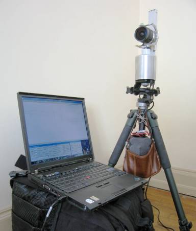
I’ve been doing that for
three years now. What started as an
amusing hack has become a full fledged photographic hobby as I discovered what
amazing pictures these cameras could make (see my web portfolio).
My first “ScanCam” turned
on the shaft of a discarded Makita sander, the rest was mostly wood and baling
wire. But it could take sharp 30
megapixel pictures; so I built a better one, then another…. I just finished my fourth
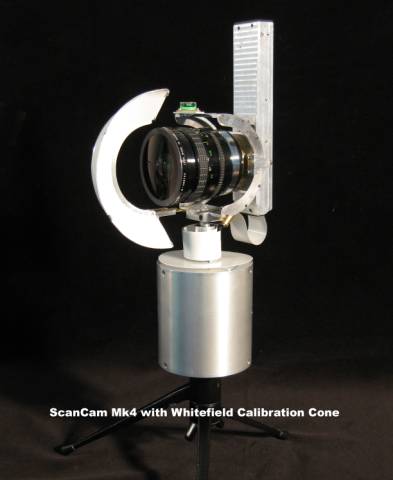
camera, based on a 7 year old 600DPI H-P Scanjet 2200c scanner. It is the first one I would rate as suitable
for daily use. The full field kit,
shown above, weighs 30 pounds including
the camera, six lenses, a sturdy tripod and head, an 18 volt NiMH
battery pack (in bag under tripod) a laptop computer, a 15 foot USB cable, a
special white calibration target, various filters, and a photographer’s
backpack to carry it all.
Scancam Mark 4 has
comparatively sophisticated mechanics as a result of lessons learned from Mark 2 and Mark 3. The most important ones are 1) the works have to be enclosed
against dust, water and static; 2) the base should be small enough to stay out
of view with the lens tilted down; 3) there must be no play in the drive mechanism
– but it must not jam, either; 4) the optical elements should be rigidly fixed
with no adjustments (minor misalignment is best corrected in software).
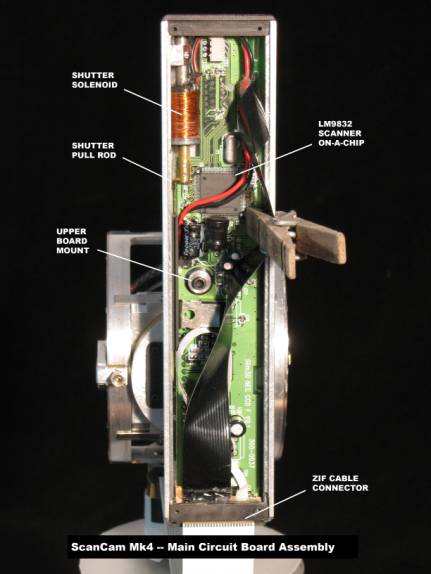
Like its predecessors. Mark
4 is controlled by a National Semiconductor LM9832, a very flexible scanner-on-a-chip
used by several scanner manufacturers in the 1999-2001 era. Because the documentation for the chip is
available to the public, I was able to develop special software for scanning
photography. This software, by now also
fairly sophisticated, works with all of my ScanCams.
The heart of a scanner is a linear CCD image sensor, one pixel wide and thousands of pixels long. The scanner’s lens and mirrors project a narrow strip of the page onto the CCD. In a camera, the CCD sees a narrow vertical strip at the center of the image formed by the lens. The CCD in the Scanjet 2200c has 5,300 pixels 0.007mm wide and the same distance apart; so Mark 4’s sensitive strip is 37.1 mm high by 0.007 mm wide. Actually there are 3 sensitive strips side by side, 0.056 mm apart, covered by red, green, and blue filters. One of the software’s jobs is to align the three colored images.
The core of Mark 4 is a
brass tube with a Minolta MD lens mount at the front end and a tall box
containing the CCD (which is mounted on the scanner’s main circuit board) at
the back.
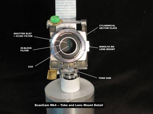
Inside the optical tube are
a round infrared blocking filter, mounted near the lens, and a tall narrow
color balancing filter mounted near the CCD.
The lens-to-CCD distance, set by machining the brass tube, is 1.7mm more
than the standard for the MD mount to allow for refraction in these filters.
The box that houses the
scanner’s main circuit board is attached to the back of the optical tube via a
round aluminum plate. A shutter, used for dark calibration, slides in a recess
in the plate, to cover a narrow slot in the box just in front of the CCD. The shutter is operated by a solenoid
connected to the scanner’s lamp power supply, which is under software control.
The CCD box is a U shaped
aluminum channel with black plastic end covers and a sliding metal back
cover. It has a thick section in front
of the CCD, with recesses for sturdy steel posts that support and locate the
circuit board. Ribbon cables inside the
box bring the scanner’s I/O port and home sensor connections to a connector on
the bottom end cover that mates with the external cable.
.
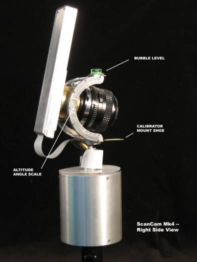
The optics tube is clamped
to a plate that slides in a semicircular yoke for tilting the lens up and
down. One side of the yoke has an engraved
scale for the lens elevation angle, and there is a bubble level on top to let
me set the camera’s rotation axis accurately vertical.
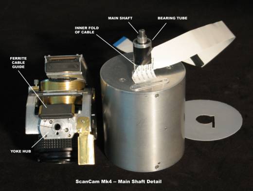
The yoke is clamped to the
top of the main shaft, which runs in
ball bearings contained in a short tube protruding from the top plate of the
cylindrical base. To allow the yoke to
rotate, the flexible ribbon cable between the two boards wraps several times
around the bearing tube. Right angle
folds at each end of the wrapped section let the ends of the cable run vertically A ferrite sleeve attached to the yoke guides
the upper end of the cable and helps suppress electrical noise. A plastic disc on top of the base keeps the
free loop of the cable from snagging when the lens is tilted up.
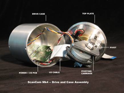
The base houses the drive mechanism
and the scanner’s power and I/O board. Its bottom plate has a tripod screw
socket in the center and holes near the edge for access to the scanner’s USB
and DC power connectors.
Mark 4 features a jam-proof
zero-backlash worm gear drive. The
primary drive train, up to the worm, is mounted on a pivoting carriage, and the worm is held in contact with the
gear by light spring pressure. The
carriage pivots are in line with its center of gravity, so that the worm won’t
lose contact with the gear when the camera tilts or moves.
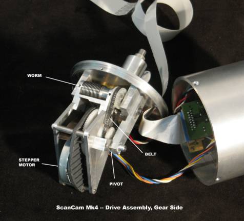
The primary drive assembly includes the
scanner’s stepping motor and main drive gear, which has a toothed belt
pulley. A short belt drives the worm
gear shaft through another toothed pulley.
The motor and main gear are on a section sawed from the scanner’s
plastic chassis, which is held between the aluminum side plates of the carriage
on two sets of tubular spacers. An
aluminum support mounted at the third corner
of the carriage holds the worm, which runs on ball bearings preloaded to
eliminate any lengthwise motion. Two
leaf springs anchored on the support plate provide the pressure that keeps the
gears in contact.
The posts that support the
carriage pivots are adjustable for height.
One of the pivots is a conical bearing whose clearance is adjusted by a
screw. By careful adjustment it is
possible to reduce the play in the pivots to near zero while aligning the worm
exactly at the center of the main gear.
The optical home position
sensor, removed from the main circuit board, is inside the drive housing. The moving vane that activates it is mounted
on a plastic pulley driven by an o-ring belt
from the hub of the main gear.
The pulley is about 50% larger than the hub, so that the shaft can turn
more than 360 degrees before the vane
reaches the sensor again.
A ScanCam differs from a
rotating film camera in several respects other than the obvious one that it is
operated by software running on a laptop computer. Perhaps most important, it is much slower. The slit in a film camera is 1-2 mm
wide, while Mark 4’s is 0.007 mm; so
the digital camera takes at least 140 times longer to capture a given image --
assuming the same photographic
sensitivity, which is only about ASA 100.
Mark 4’s maximum resolution
is nearly 18 megapixels per 35mm frame, so in practice I take most scans at
half resolution. That cuts the scan
time by a factor of 4, but it is still long.
For example, a 360 degree scan at half resolution in daylight with a
24mm wide angle lens takes 3 minutes and captures 27 million pixels. But I often take 10 minute scans, and
occasionally 30 minute ones.
Since the CCD length is
about equal to the width of a 35mm frame, Mark 4’s images are comparable to
stitched panoramas made from “portrait format” 35mm photos. On that basis, a 360 degree scan with the
24mm lens is equivalent to 6½ normal
photos with no overlap, or 10 with enough overlap for stitching.
A very significant
difference from film cameras is that ScanCams need to be calibrated before scanning. Even cheap scanners deliver amazing image
quality mainly because they correct defects in their sensors and optics as
follows. Before each scan, measure the sensor’s raw responses to black
and white calibration strips. During
the scan, correct each pixel by subtracting its black response, then
multiplying by a factor inversely proportional to its white response. The result is a very uniform corrected response, flatter than a film
camera’s because the white calibration also removes lens shading; but most
important, it corrects for dust and optical imperfections on the CCD.
Duplicating that procedure
is the most critical aspect of ScanCam operation.
It is easy to get black
calibration data. My ScanCams do it
automatically, using an electrically operated shutter to put the CCD in the
dark.
White calibration is
harder, especially with wide angle lenses.
It requires manually placing a suitable target in front of the lens.
that projects a uniform white field on the CCD. Flat targets such as white cards or ground glass work all right
with long lenses, but do not light the periphery correctly with short
ones. The best all purpose target I
have been able to devise (shown in the first photo above) is a sector of a cone
made of white paper, held in a curved aluminum frame. When evenly lit from the side, it puts a very flat white field on the CCD, even with wide angle and
fisheye lenses.
I do the white calibration
in two stages. First, in the studio I
light the conical target very uniformly, and record each lens’s shading curves
at several apertures. The software
stores field flattening files that are later reloaded when I set the aperture
for taking a picture. Just before
scanning I do a “dust” calibration, which removes localized defects (typically
due to dust specks) without changing the overall shape of the correction
curve. At this stage the target image
doesn’t have to be perfectly flat, just smooth and featureless – I can often
use a strip of milky white plastic, a
ground glass filter, or an out of focus wall instead of the cone target.
Both aspects of the white
field correction depend on lens aperture.
The shading correction changes most at large openings and is essentially
constant below f/5.6. At small apertures
the dust correction is large and varies strongly with aperture; it becomes
constant (and often negligible) at large ones.
As a practical matter, the dust correction is essential for good outdoor
pictures and often unnecessary for indoor ones since the field flattening curves
also correct intrinsic pixel-to-pixel sensitivity differences.
An advantage over most
rotating film cameras is that the ScanCam takes interchangeable lenses, so can
make panoramas in a wide range of formats from near-spherical to very long and
thin, as well as high resolution rectangular images. I use 6 lenses on Mark 4, ranging from an 8mm fisheye (image
height 180 degrees, but only 3700 pixels) to a 55mm (image height 37 degrees,
5300 pixels). I use a 16mm fisheye
(image height 153 degrees, 5300 pixels) for “superwide” and “supertall”
architectural pictures, the 55mm for classic panoramic landscapes, and 24, 28
and 35mm lenses for close to medium
distance work.
Having lots of pixels and a
wide choice of angular resolutions makes ScanCam pictures natural raw material
for reworking on the computer. I use
the Dersch PanoTools and some programs of my own based on Dersch’s source code
to adjust viewing perspectives, sometimes radically and sometimes subtly, to make
images better represent their subjects as I (would like to) see them. I sometimes stitch multiple scans into even
larger images, and sometimes combine different versions of a scene in
Photoshop.
A rotating camera is ideal
for imaging buildings because it renders all vertical lines as true verticals. Unfortunately there is a color-dependent
image curvature at large elevation angles that is inherent in the rotating
camera geometry and can’t be corrected physically in the camera. However with the digital camera it is fairly
easy to correct this defect in software.
The corrections depend on the exact degree of misalignment between the
CCD and the rotation axis, so I calibrate them by scanning tall TV towers from
close up with a fisheye lens, and adjusting the parameters in my correction
program until the tops of the towers are straight and free of color
fringes. Then I can make dramatic photos of buildings from close up. In the example below the camera was about 40
feet from the near corner of the building.

One of the few things that
film can do better than CCDs is tolerate local overexposure. Camera CCDs have
expensive “antiblooming” circuits that keep the excess charge in badly
overexposed pixels from damaging too many of their properly exposed neighbors.
But even then the spoiled area is typically larger than it would be on a good
film. Worse, the damage takes the form
of long streaks of whited-out pixels
rather than compact blobs.
Unfortunately, scanner CCDs don’t have antiblooming circuits at all, so
that even one pixel overexposed by 2 stops or more spoils a whole column of the
image. That makes ScanCams useless for
high dynamic range imaging, and hard to take normal pictures with as well. Any well lit scene is apt to contain a few
bright reflections, perhaps quite small, that will throw nasty streaks across a
ScanCam image; and windows regularly wreck interior shots. I have to be extremely careful to avoid that
sort of thing, and often have to underexpose the parts I’m interested in just
to avoid having a bit of the sky blow them away altogether. Of course motion and unsteady lighting also
spoil ScanCam images (though some kinds of motion artifacts are amusing or even
beneficial) so I have to be very careful about the subject and the weather as
well.
The bottom line is that
this is a very deliberate kind of
photography, that puts a premium on careful observation and planning as
well as luck. But maybe that’s true for
other modes of panoramic photography, too.